The configuration tasks on the
High Availability
> Advanced
page are performed on the Primary unit and then are automatically synchronized to the Backup.
To configure the settings on the
High Availability
> Advanced
page, perform the following steps:
When Stateful High Availability is not enabled, session state is not synchronized between the
Primary and Backup SonicWALL security appliances. If a failover occurs, any session that had been active at the time of failover needs to be renegotiated.
When Stateful High Availability is not enabled, it is not possible to enable the Active/Active UTM
feature.
|
Step 4
|
Click
OK
in the Stateful Synchronization recommended settings dialog box.
|
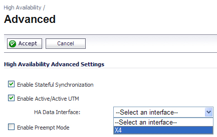
The selected interface must be the same one that you physically connected as described in
“
Initial Active/Active UTM Setup
”
.
|
Step 9
|
Select the
Enable Virtual MAC
checkbox. Virtual MAC allows the Primary and Backup appliances to share a single MAC address. This greatly simplifies the process of updating network ARP tables and caches when a failover occurs. Only the switch to which the two appliances are connected needs to be notified. All outside devices will continue to route to the single shared MAC address.
|
|
Step 10
|
Optionally adjust the
Heartbeat Interval
to control how often the two units communicate. The default is 5000 milliseconds; the minimum supported value is 1000 milliseconds. You can use higher values if your SonicWALL handles a lot of network traffic.
|
|
Step 11
|
Set the
Failover Trigger Level
to the number of heartbeats that can be missed before failing over. The default is 5.
|
|
Step 12
|
Set the
Probe Interval
to the interval in seconds between probes sent to specified IP addresses to monitor that the network critical path is still reachable. This is used in logical monitoring. SonicWALL recommends that you set the interval for at least 5 seconds. The default is 20 seconds, and the allowed range is 5 to 255 seconds. You can set the Probe IP Address(es) on the High Availability
> Monitoring
screen. See “
High Availability > Monitoring
”
.
|
|
Step 13
|
Set the
Probe Count
to the number of consecutive probes before SonicOS Enhanced concludes that the network critical path is unavailable or the probe target is unreachable. This is used in logical monitoring. The default is 3, and the allowed range is 3 to 10.
|
|
Step 14
|
Set the
Election Delay Time
to the number of seconds allowed for internal processing between the two units in the High Availability Pair before one of them takes the Primary role. The default is 3 seconds.
|
|
Step 15
|
Set the
Dynamic Route Hold-Down Time
to the number of seconds the newly-Active appliance keeps the dynamic routes it had previously learned in its route table. This setting is used when a failover occurs on a High Availability pair that is using either RIP or OSPF dynamic routing. When a failover occurs, Dynamic Route Hold-Down Time
is the number of seconds the newly-Active appliance keeps the dynamic routes it had previously learned in its route table. During this time, the newly-Active appliance relearns the dynamic routes in the network. When the Dynamic Route Hold-Down Time
duration expires, it deletes the old routes and implements the new routes it has learned from RIP or OSPF. The default value is 45 seconds. In large or complex networks, a larger value may improve network stability during a failover.
|
|
|
Note
|
The
Dynamic Route Hold-Down Time
setting is displayed only when the Advanced
Routing
option is selected on the Network > Routing
page.
|
|
Step 16
|
Select the
Include Certificates/Keys
checkbox to have the appliances synchronize all certificates and keys.
|
|
Step 17
|
You do not need to click
Synchronize Settings at this time, because all settings will be
automatically synchronized to the Idle unit when you click Accept after completing HA
configuration
. To
synchronize all settings on the Active unit to the Idle unit immediately, click Synchronize Settings
. The Idle unit will reboot.
|
|
Step 18
|
Click
Synchronize Firmware
if you previously uploaded new firmware to your Primary unit while the Backup unit was offline, and it is now online and ready to upgrade to the new firmware. Synchronize Firmware
is typically used after taking your Backup appliance offline while you test a new firmware version on the Primary unit before upgrading both units to it.
|
If you enabled Active/Active UTM, the Network > Interfaces page will show that the selected
interface for HA Data Interface
now belongs to the HA Data-Link
zone.